ImFusion SDK 4.3

Modern geometrical framework for cone-beam X-ray acquisitions. More...

+ Collaboration diagram for Cone Beam Geometry:

Detailed Description

Modern geometrical framework for cone-beam X-ray acquisitions.
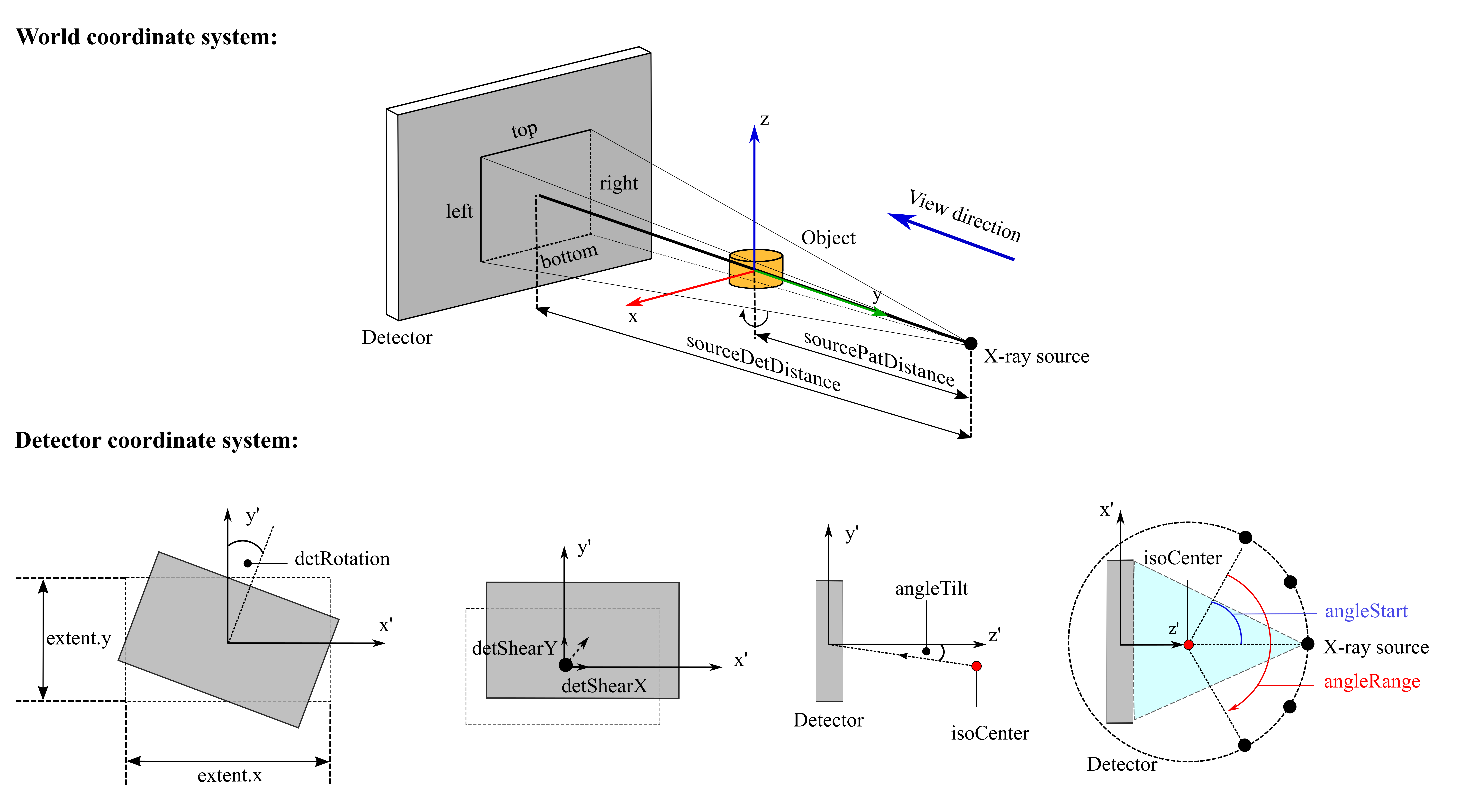
Overview of the main geometry parameters
Note
In the visualization:
  • Detector coordinate system follows OpenGL convention.
  • In all images, the other parameters are assumed to be zero.
  • extent.x, extent.y only represent physical size of the image, not the "image" coordinate system.

We refer to a single X-ray image taken with a point source as a "cone-beam" image. A set of such cone-beam images is described by a CT::ConeBeamData object. CT::ConeBeamMetadata DataComponent which contains the geometry information is attached to the CT::ConeBeamData object. This system is used to describe circular acquisition geometries as used in cone-beam CT, but can also be used to describe the geometry of sets of more-general X-ray images.

Mathematically, cone-beam images are equivalent to pinhole camera images. The intrinsic parameters between individual shots often do not vary in an acquisition. The acquisition geometry of such a set can be described using the modern geometry system with per-frame flexibility, or with the legacy CT::ConeBeamGeometry class for backward compatibility.

Before working with cone-beam geometry, it is essential to understand the coordinate system conventions used throughout the ImFusion CT module.

Coordinate system conventions

ImFusion SDK supports three different coordinate systems, please refer to CoordinateSystems for more details.

Coordinates of a point are often transformed back and forth between coordinate systems for particular use cases. Therefore, it is crucial to define the coordinate system of a specific context.

Perspective of an X-ray image

By default, ImFusionCT considers an X-ray image viewed from the source towards the detector plane.

Based on this perspective, the left/right sides of the image correspond to the left/right sides of the viewer, and the top/bottom refer to the upper/lower sides of the image relative to the viewer's eyes.

Coordinate conventions of the 2D (X-ray) image

Similarly to ImFusion SDK Coordinate Systems, ImFusionCT also makes use of four coordinate conventions for X-ray images.

X-ray coordinate conventions

X-ray cone-beam geometry

Standard coordinate systems

There are two separate coordinate systems considered in this context, world coordinate system and detector coordinate system.

The followings define the two 'standard' coordinate systems without any further transformations.

World coordinate system

Detector coordinate system in OpenGL convention (default)

Detector coordinate system in OpenCV

Note
For more details on other detector coordinate conventions and conversion between them, check Coordinate system conventions and Matrix section.

X-ray acquisition settings

There are various acquisition geometries corresponding to different X-ray CT scanners. The geometry can be defined by explicitly providing the projection matrices, using parametric generators, or through manual per-frame setup.

The modern geometry system supports both OpenGL and OpenCV matrix conventions for import and export. Internally, matrices follow the OpenGL convention but the system provides convenient conversion functions between the two conventions.

Matrix operations

The full OpenGL projection matrix transforms 3D points to 2D points in OpenGL clip coordinates (see Coordinate system conventions section).

The geometry system provides seamless conversion between OpenGL and OpenCV matrix formats through the CT::GeometryUtils namespace, supporting both import from and export to either convention with comprehensive utility functions for all common matrix operations.

One can use the utility functions CT::Utils::project(), CT::Utils::backproject() to compute the forward/backward projections of points using the matrices.

Modern Geometry System

The modern geometry system in ImFusion CT is built around flexible, per-frame geometry representations that can handle arbitrary acquisition setups. The system uses data components to store geometry information and generators to create e.g. parametric acquisition patterns.

Setting up \ref ConeBeamData

First, convert your SharedImageSet to Cone Beam Data and enable the modern geometry system:

#include <ImFusion/CT/ConeBeamMetadata.h>
#include <ImFusion/CT/Geometry/ParametricGeometryGenerator.h>
#include <ImFusion/CT/Geometry/GeometryDataComponents.h>
// Convert SharedImageSet to \ref ConeBeamData
CT::makeConeBeamData(sharedImageSet);
// Get the cone-beam metadata and enable modern geometry
CT::ConeBeamMetadata& metadata = CT::ConeBeamMetadata::get(sharedImageSet);
metadata.enableModernGeometry();
static const ConeBeamMetadata & get(const SharedImageSet &sis)
Shortcut to get ConeBeamMetadata from a SharedImageSet.

ParametricGeometryGenerator

For common acquisition patterns (e.g. circular trajectories), use the CT::ParametricGeometryGenerator:

// Create and configure parametric geometry generator
CT::ParametricGeometryGenerator paramGen;
paramGen.sourceDetDistance = 1200.0; // Source to detector distance (mm)
paramGen.sourcePatDistance = 700.0; // Source to patient distance (mm)
paramGen.angleRange = 180.0; // Angular range (degrees)
// Configure iso parameters
auto& transformSetup = paramGen.transformationSetup;
transformSetup.useIsoCenterParameters = true;
transformSetup.isoRotation = {-30.0, 0.0, 45.0}; // Euler angles (degrees)
// Add generator to metadata
metadata.addGenerator(paramGen, true); // true = select as active generator

Manual Per-Frame Geometry

For custom acquisition patterns, set geometry manually per frame:

#include <ImFusion/CT/Geometry/GeometryDataComponents.h>
for (int i = 0; i < sharedImageSet.size(); ++i) {
// Get or create source data component for frame i
CT::SourceDataComponent& sourceData = CT::SourceDataComponent::getOrCreate(sharedImageSet, i);
// Set source position in detector coordinate system
sourceData.locationSourceInDetectorSpace = {0.0, 0.0, -1200.0};
// Get or create detector data component for frame i
CT::DetectorDataComponent& detectorData = CT::DetectorDataComponent::getOrCreate(sharedImageSet, i);
// Set transformation matrix from world to detector coordinates
mat4 transformMatrix = mat4::Identity();
// Example: rotate around Y axis based on frame index
double angle = 90.0 * i / (sharedImageSet.size() - 1) * M_PI / 180.0;
transformMatrix.block<3,3>(0,0) = Eigen::AngleAxisd(angle, vec3::UnitY()).toRotationMatrix();
detectorData.matrixWorldToDetector = transformMatrix;
}
static DetectorDataComponent & getOrCreate(SharedImageSet &sis, int frame)
Get or create the DetectorDataComponent for a given frame in a SharedImageSet.
static SourceDataComponent & getOrCreate(SharedImageSet &sis, int frame)
Get or create the SourceDataComponent for a given frame in a SharedImageSet.

Matrix Conversion and Reconstruction

The modern geometry system supports bidirectional conversion between OpenGL and OpenCV matrix conventions through the CT::GeometryUtils namespace. These utilities provide comprehensive matrix conversion capabilities.

Converting TO Modern Geometry Representation (e.g. from projection matrices)

#include <ImFusion/CT/Geometry/GeometryUtils.h>
// Create geometry from OpenGL matrix
mat4 openglProjectionMatrix = /* your 4x4 OpenGL matrix */;
vec2 detectorSize = {300.0, 300.0}; // detector size in mm
openglProjectionMatrix, detectorSize);
// Alternative: Create with pixel information
int width = 1024, height = 1024;
vec2 pixelSpacing = {0.3, 0.3}; // mm per pixel
openglProjectionMatrix, width, height, pixelSpacing);
// Create geometry from OpenCV matrix
mat34 opencvProjectionMatrix = /* your 3x4 OpenCV matrix */;
opencvProjectionMatrix, width, height, pixelSpacing);
// Apply geometry to SharedImageSet frame
CT::GeometryUtils::applyFullGeometryRepresentation(sharedImageSet, geomFromGl, frameIndex);
// Or apply to all frames
std::vector<CT::GeometryUtils::FullGeometryRepresentation> allGeometries = {geomFromGl, geomFromCv};
FullGeometryRepresentation frameGeometryFromOpenCVMatrix(const mat34 &matrix, int width, int height, const vec2 &pixelSpacing)
Converts an OpenCV projection matrix to FullGeometryRepresentation.
void applyFullGeometryRepresentation(SharedImageSet &sis, const FullGeometryRepresentation &geom, int frame)
Apply FullGeometryRepresentation to a single frame of a SharedImageSet.
FullGeometryRepresentation frameGeometryFromOpenGLMatrix(const mat4 &matrix, const vec2 &detSize)
Converts an OpenGL projection matrix to FullGeometryRepresentation.

Converting FROM Modern Geometry Representation (e.g. to projection matrices)

// Get geometry representations for all frames
auto perFrameGeometries = CT::GeometryUtils::perFrameGeometry(sharedImageSet);
for (int i = 0; i < perFrameGeometries.size(); ++i) {
const auto& geom = perFrameGeometries[i];
// Extract OpenCV matrices and components
mat3 K, R;
vec3 t;
// Get OpenCV camera parameters (pixel coordinates)
// Get full OpenCV projection matrix (pixel coordinates)
mat34 opencvMatrix = CT::GeometryUtils::matrixOpenCVToPixel(geom);
// Get OpenCV matrices in image coordinates (mm, center origin)
auto [K_img, R_img, t_img] = CT::GeometryUtils::matrixComponentsOpenCVToImage(geom);
mat34 opencvImageMatrix = CT::GeometryUtils::matrixOpenCVToImage(geom);
// Extract OpenGL matrices
mat4 projMatrix, modelViewMatrix;
std::tie(projMatrix, modelViewMatrix) = CT::GeometryUtils::matrixComponentsGl(geom);
// Get full OpenGL projection matrix
mat4 openglMatrix = CT::GeometryUtils::matrixGlToImage(geom);
// Get OpenGL matrix with top-left origin (for texture coordinates)
mat4 openglTopLeft = CT::GeometryUtils::matrixGlToImageTopLeft(geom);
// Extract additional geometry information
vec3 sourceWorldPos = CT::GeometryUtils::sourcePositionWorld(geom);
double sourceDetDist = CT::GeometryUtils::sourceToDetectorDistance(geom);
}
vec3 sourcePositionWorld(const FullGeometryRepresentation &geom)
Return source position in world coordinates.
mat4 matrixGlToImage(const FullGeometryRepresentation &geom)
Return full projection matrix in OpenGL convention (.
mat4 matrixGlToImageTopLeft(const FullGeometryRepresentation &geom)
Returns the projection matrix from matrix() but with the y-axis being flipped as we use a top-left sy...
std::vector< FullGeometryRepresentation > perFrameGeometry(const SharedImageSet &sis)
Collect the perFrameGeometry for all frames in a given SharedImageSet.
std::tuple< mat3, mat3, vec3 > matrixComponentsOpenCVToPixel(const FullGeometryRepresentation &geom)
Return K (to image (px)), R, t in OpenCV convention represented by this ConeBeamGeometry.
double sourceToDetectorDistance(const FullGeometryRepresentation &geom)
Returns the sourceToDetectorDistance in mm.
std::tuple< mat4, mat4 > matrixComponentsGl(const FullGeometryRepresentation &geom)
Return projection matrices in OpenGL convention, i.e. PM and MV.
mat34 matrixOpenCVToImage(const FullGeometryRepresentation &geom)
Return P = K (to image (mm)) * [R | t] in OpenCV convention represented by this ConeBeamGeometry.
std::tuple< mat3, mat3, vec3 > matrixComponentsOpenCVToImage(const FullGeometryRepresentation &geom)
Return K (to image (mm)), R, t in OpenCV convention represented by this ConeBeamGeometry.
mat34 matrixOpenCVToPixel(const FullGeometryRepresentation &geom)
Return P = K (to image (px)) * [R | t] in OpenCV convention represented by this ConeBeamGeometry.
T tie(T... args)

Direct SharedImageSet Access

For convenience, all conversion functions are also available with direct SharedImageSet access:

// Direct access to matrices from SharedImageSet
for (int frame = 0; frame < sharedImageSet.size(); ++frame) {
// OpenCV matrices
auto [K, R, t] = CT::GeometryUtils::matrixComponentsOpenCVToPixel(sharedImageSet, frame);
mat34 opencvProj = CT::GeometryUtils::matrixOpenCVToPixel(sharedImageSet, frame);
// OpenGL matrices
mat4 openglProj = CT::GeometryUtils::matrixGlToImage(sharedImageSet, frame);
auto [projMat, modelMat] = CT::GeometryUtils::matrixComponentsGl(sharedImageSet, frame);
// World transformations
mat4 worldToImage = CT::GeometryUtils::matrixFromWorldToImage(sharedImageSet, frame);
mat4 imageToWorld = CT::GeometryUtils::matrixFromImageToWorld(sharedImageSet, frame);
// Geometry properties
vec3 sourcePos = CT::GeometryUtils::sourcePositionWorld(sharedImageSet, frame);
double focal = CT::GeometryUtils::sourceToDetectorDistance(sharedImageSet, frame);
}
mat4 matrixFromImageToWorld(const FullGeometryRepresentation &geom)
Returns transformation matrix from image to world.
mat4 matrixFromWorldToImage(const FullGeometryRepresentation &geom)
Returns transformation matrix from world to image.

Legacy Geometry Conversion

Convert between legacy CT::ConeBeamGeometry and modern representation:

// Synchronize legacy geometry to modern per-frame representation
metadata.syncToModernGeometry();

Non-standard Detectors

The modern system supports various detector types through CT::DetectorPropertiesDataComponent:
// Get or create detector properties
CT::DetectorPropertiesDataComponent& detectorProps =
// Configure flat panel detector (default)
detectorProps.curvature = CT::DetectorCurvature::FLAT;
// Configure fan-beam detector
detectorProps.curvature = CT::DetectorCurvature::FANFLAT;
// Configure curved cylindrical detector
detectorProps.curvature = CT::DetectorCurvature::CYLINDRICAL;
detectorProps.radii = {800.0, 800.0}; // Curvature radii per frame
detectorProps.curvedOffsets = {
{0.4, 0.4}, // Offset for frame 0
{0.4, 0.4} // Offset for frame 1
};
static const DetectorPropertiesDataComponent & getOrCreate(const SharedImageSet &sis)
Shortcut to get or create DetectorPropertiesDataComponent from a SharedImageSet.
Non-standard detectors

Curved detector geometry

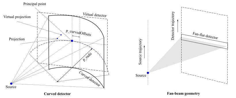
ImFusionCT supports curved detector geometry through the DetectorPropertiesDataComponent. In this non-standard detector acquisition, it is assumed that the 3D points are first projected on a virtual flat-panel detector and corrected for the real detector curvature afterwards.

All geometry settings for an acquisition with a curved detector can be given directly through the matrices or parameters as for a circular geometry.

The DetectorPropertiesDataComponent::Curvature allows specifying different types of detector for a data acquisition:

For curved detectors, additional parameters are required:

Example setup for curved detector:

// The following demonstrates setting up a curved detector with a radius of 50 mm,
// and an offset of 10.0 mm to the virtual detector center.
detectorProps.curvature = CT::DetectorCurvature::CYLINDRICAL;
detectorProps.radii = {50.0}; // radii of the cylindrical curve
detectorProps.curvedOffsets = {{10.0, 0.0}};

The curved detector uses the matrices as for the flat-panel detector to compute forward/backward projections of a point and compensates for the detector curvature afterwards.

We use the representation with projection matrices to define a virtual detector plane. This virtual detector is tangent to the curved detector at the principal point. The point on the virtual detector represents the arclength on the curved detector, i.e. the virtual detector is "rolled" onto the curved one.

Fan-beam geometry (fan-flat detector)

A fan-beam acquisition is the X-ray CT acquisition where the source/detector moves along an axis while the X-ray fan-flat beams are emitted. Fan-beam geometry setting can be enabled through DetectorPropertiesDataComponent:

// Enable fan-beam geometry
detectorProps.curvature = CT::DetectorCurvature::FANFLAT;
// Or through legacy ConeBeamGeometry
legacyGeom.useFanBeam = true;

This is commonly used in 2D CT scanners and some dental imaging systems.

Utility Functions

The CT module provides utility functions for common geometric operations:

#include <ImFusion/CT/Utils.h>
// Project 3D point to 2D detector coordinates
vec3 worldPoint = {10.0, 5.0, 0.0};
vec2 detectorCoords = CT::Utils::project(worldPoint, geom, detectorProps);
// Back-project 2D detector point to 3D ray
vec2 detectorPoint = {100.0, 50.0};
std::pair<vec3, vec3> ray = CT::Utils::backproject(detectorPoint, geom, detectorProps);
// ray.first = origin, ray.second = direction
std::vector< vec2 > project(SharedImageSet &cbData, int frame, std::vector< vec3 > in, ImageMath::CoordinateType coordinateType2d=ImageMath::CoordinateType::Texture)
project 3D points onto a 2D plane, coordinate type of result is given by the coordinateType2d paramet...
std::vector< Geometry::LineSegment > backproject(const SharedImageSet &cbData, int frame, std::vector< vec2 > in, ImageMath::CoordinateType coordinateType2d=ImageMath::CoordinateType::Texture)
Computes the ray (world coordinates) from the source to a detector point, given by coordines in the d...

Legacy ConeBeamGeometry Support

For backward compatibility, the legacy CT::ConeBeamGeometry is still supported but not recommended for new projects:

#include <ImFusion/CT/Legacy/ConeBeamGeometry.h>
// Disable modern geometry to use legacy system
metadata.disableModernGeometry();
// Get legacy geometry object
CT::ConeBeamGeometry& legacyGeom = metadata.geometry();
// Configure legacy parameters
legacyGeom.sourceDetDistance = 1000.0;
legacyGeom.sourcePatDistance = 500.0;
legacyGeom.detSizeX = 300.0;
legacyGeom.detSizeY = 300.0;
legacyGeom.angleRange = 90.0;
legacyGeom.reconRotX = 0.0;
legacyGeom.reconRotY = 0.0;
legacyGeom.angleStart = 45.0;
// Legacy matrix access
mat4 legacyMatrix = legacyGeom.matrix(frameIndex, numFrames);
// Load matrices from text file (legacy)
// Each line holds an OpenCV projection matrix entry (12 coefficients/row) for a single frame, row-major
bool isLoaded = legacyGeom.loadMatrices("path_to_matrix_file.txt", imgWidth, imgHeight);
// Get model matrix (per-frame transformations of source/detector)
mat4 modelViewMatrix = legacyGeom.modelMatrix(frameIndex, numFrames);
Note
The legacy ConeBeamGeometry has limited flexibility compared to the modern geometry system. New projects should use the modern geometry components for maximum flexibility and future compatibility.

Migration from legacy CT::ConeBeamGeometry to modern geometry

To migrate existing code from legacy to modern geometry:

  1. Replace metadata.geometry() calls with geometry generators or manual per-frame setup
  2. Use CT::GeometryUtils::matrixGlToImage() instead of geometry.matrix()
  3. Use SourceDataComponent and DetectorDataComponent for frame-specific geometry

The modern system provides equivalent functionality with greater flexibility and cleaner separation of concerns.

Common acquisition geometries and parameterization

Circular geometry

A common X-ray CT acquisition geometry follows a circular trajectory where the source/detector rotate around the patient. Apart from providing the matrices explicitly, the circular geometry can be directly parameterized by geometry parameters.

The source/detector arc

These parameters are defined with respect to the standard world coordinate system. In such standard setting, the 'patient' (or 'iso-center') is at the center of the arc. Without further configuration, the iso-center is at the point (0, 0, 0).

legacyGeom.sourceDetDistance = 1200.0; // Distance between detector plane and X-ray source
legacyGeom.sourcePatDistance = 700.0; // Radius of circular arc that X-ray source makes
legacyGeom.angleRange = 180.0; // Rotational range (degrees) that arc spans

The source/detector translation and rotation (Legacy)

The detector-related parameters are defined with respect to the standard detector coordinate system:

legacyGeom.detShearX // Translation of detector along x'-axis
legacyGeom.detShearY // Translation of detector along y'-axis
legacyGeom.detRotation // Detector rotation about the z'-axis (applied after shear)
legacyGeom.angleTilt // Angle between central ray and z'-axis
legacyGeom.detOffsetX // Additional horizontal offset for both detector and source

The angleTilt parameter acts the same way as detShearY after applying:

tan(angleTilt) * sourceDetDistance

Iso matrix transformations

The isoMatrix is the rigid transformation (rotation, translation) matrix of the iso-center (CT volume):

// Set/get iso matrix directly
legacyGeom.setIsoMatrix(mat4);
mat4 isoMat = legacyGeom.isoMatrix(i, numFrames);
// Or manipulate through geometry parameters
legacyGeom.reconRotX // Reconstruction volume rotation around X-axis (degrees)
legacyGeom.reconRotY // Reconstruction volume rotation around Y-axis (degrees)
legacyGeom.angleStart // Starting angle (degrees)
legacyGeom.reconOffsetX // Reconstruction volume translation along X-axis
legacyGeom.reconOffsetY // Reconstruction volume translation along Y-axis
legacyGeom.reconOffsetZ // Reconstruction volume translation along Z-axis
// Set rotation center
legacyGeom.isoMatRotCtr = vec3(2.0, 1.0, 0.5);

The orientation and position of the reconstruction volume relative to the standard world coordinate system are represented by these rotation and translation parameters.

Namespaces

namespace  ImFusion
 Namespace of the ImFusion SDK.
 
namespace  ImFusion::CT
 X-ray and computed tomography.
 
namespace  ImFusion::CT::SpecificProjectionGeometries
 Predefined geometries for specific imaging systems.
 
namespace  ImFusion::CT::GeometryUtils
 Utility functions for geometry processing and manipulation.
 

Classes

class  ConeBeamCalibration
 Geometric calibration algorithm for X-ray imaging systems. More...
 
class  CopyConeBeamGeometryAlgorithm
 Algorithm for copying cone-beam geometry between datasets. More...
 
class  GeometryGeneratorOptimizingAlgorithm
 Optimizing algorithm for cone-beam geometry parameter estimation. More...
 
class  ProjectionMatrixIoAlgorithm
 I/O algorithm for saving and loading projection matrices. More...
 
class  FullGeometryRepresentationWrapper
 
class  SnapshotGenerator
 Geometry generator for capturing current geometric state. More...
 
class  RelativeGeneratorMixin< T >
 Template mixin for relative geometry generators. More...
 
class  MotionModelGenerator
 Geometry generator using motion models for complex trajectories. More...
 
class  GlobalTransformationGeneratorBase
 Base class for global transformation generators. More...
 
class  RelativeGlobalTransformationGenerator
 Geometry generator for single relative transformation applied to all frames. More...
 
class  PerFrameTransformationGeneratorBase
 Base class for per-frame transformation generators. More...
 
class  RelativePerFrameTransformationGenerator
 Geometry generator for individual relative transformations per frame. More...
 
class  DetectorPropertiesDataComponent
 Data component for detector properties and configuration Stores detector-specific parameters and settings for cone-beam systems. More...
 
class  GeometryAlgorithm
 Algorithm for applying geometry settings to cone-beam data. More...
 
class  SourceDataComponent
 Data component for cone-beam X-ray source parameters. More...
 
class  DetectorDataComponent
 DataComponent to store the transformation from world to detector space for a single frame. More...
 
class  GeometryGenerator
 Base class for X-ray geometry generators. More...
 
class  GeometryGeneratorParameterWrapper
 Parameter wrapper for geometry generator optimization. More...
 
class  ParametricGeometryGenerator
 Parametric geometry generator for regular CBCT acquisition trajectories. More...
 
struct  RelativeTransformationConfig
 Configuration structure for relative transformation setup. More...
 
struct  RelativeTransformationSetupWrapperBase
 Base class for RelativeTransformationSetupWrapper which requires customer move and copy semantics due to signal connections it creates. More...
 
class  RelativeTransformationSetupWrapper
 This class handles signal connections and ensures reconnecting after copying etc. More...
 
class  ConeBeamDisplayOptions
 Data component for cone-beam display configuration. More...
 
Search Tab / S to search, Esc to close